


- HYDRAULIC PRESSURE INTENSIFIERS

|
|
||||||||||||||
|
|
||||||||||||||
|
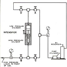
ILLUSTRATING THE USE OF THE HYDRAULIC PRESSURE INTENSIFIER |
||||||||||||||
|
With valves C and D closed and valves A and B open, oil is pumped from the reservoir through valve A into the low-pressure end of the intensifier. High-pressure oil from the high-pressure end of the intensifier passes out through valve B to the point of use. Pumping is continued until the intensifier piston reaches the top of its stroke as indicated by a rapid increase in pressure on the primary side of the intensifier. The piston must then be returned to the bottom of its stroke.
Valves A and B are first closed to retain high pressure at the point of use and valves C and D are opened. Oil from the pump enters the high-pressure end of the intensifier through valve C to force the piston down and drive oil from the low-pressure end of the intensifier through valve D and back to the oil reservoir. The cycle is repeated as often as is necessary to build up the required pressure at the poi
nt of use.
|
||||||||||||||
|
HYDRAULIC PRESSURE INTENSIFIERS |
||||||||||||||
|
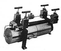
Hydraulic Pressure Intensifiers are used for creating pressures greater than those ordinarily obtained directly from either Hand Operated Pumps or Motor Driven Pumps. While not intended for high volumetric capacity, their simplicity of design makes then an economical means of obtaining high pressure. The intensifier consists of a double piston-cylinder arrangement as shown in the sectional view. Oil is pumped into the large cylinder by a hand hydraulic pump or other means, and oil is expelled from the small cylinder at a higher pressure, dependent upon the area ration and friction. The large piston is fitted with an O-ring for maximum efficiency at the pressures encountered in the cylinder. The small piston is lapped to an extremely close fit and is packed with a combination packing on the principle of the unsupported area. Due to the necessary close fit of the pistons in their respective cylinders, the friction created does not permit 100% efficiency as calculated from the ratio. Hydraulic intensifiers are manufactured in two basic models for producing pressures of 50,000 and 100,000 psi. Their construction is similar except that the 100,000 psi model is built with heavier cylinders and pistons.
Each of these models is available either as a complete assembly with valves as illustrated or as the cylinder and piston assembly shown in the sectional view.
|
||||||||||||||
|
INTENSIFIER COMPLETE WITH 1/4-INCOUPLINGS, 4 CONTROL VALVES, AND 3 TEES IN A SELF-SUPPORT FRAME
|
||||||||||||||
|
CYLINDER AND PISTON ASSEMBLY ONLY WITH 1/4-IN. COUPLINGS
|
||||||||||||||
SPECIFICATIONS AND ORDER INFORMATION
| Catalog Number | Product Name | Product Description | Add To Cart |
|---|---|---|---|
| 46-19229 | 0-50K Hydraulic Pressure Intensifier | Not Available |
 Add To Cart Add To Cart |
| 46-19230 | 0-50K Hydraulic Pressure Intensifier Cylinder & Piston Assy Only | Not Available |
Add To Cart |
| 46-19252 | 0-100K Hydraulic Pressure Intensifier | Not Available |
Add To Cart |
| 46-19253 | 0-100K Hydraulic Pressure Intensifier Cylinder & Piston Assy Only | Not Available |
Add To Cart |
 Download the Manual